Yes, you read the title right. Instead of XSLT
transformer, I’m doing a real world transformation this time.
SOA 12C has not caught on fire; posting old stuff is getting boring.
So I thought I'll pick up a new topic for a change.
I bought a Danby chest freezer last year. They are not
kidding when they called it a freezer. Although it came with a temperature
dial, the highest temp you can set is way below freezing. It is puzzling to me
why won't they provide a wider temp range so user can operate it either as a
freezer or fridge.
I thought there would be an easy way to rig the temp control
somewhere to fool the system. After searching online, I found out there is no
easy trick. I decided to bite the bullet and give it a try to replace the controller myself. It was quite
an enlightening experience. I stumbled on so many trivial things that pros
didn’t bother to mention, after I overcame those problems, I thought I would
share it so it may benefit other amateurs like me.
I ordered an 110V STC 1000 digital temp controller for about
$23 (including shipping) from amazon.com.
When I opened the box, I got more questions than answers. After much
online reading, a few trips to RadioShack and Home Depot, this is what I
finally sorted out:
How does the existing
controller work?
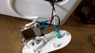
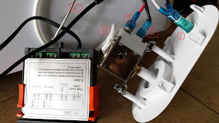
The picture on the left shows the original controller. The picture below shows the STC-1000 controller (on the left) next to the original, It's not wired yet.
The original sensor came with a metal probe, that metal probe (I circled #4 on the drawing below) is directly linked to the controller with a white insulated line circled #5. The white cover is the temperature insulation, I believe that mechanical temperature sensor relies on that probe to transmit some chemical gas pressure based on the temperature change inside the freezer. That also explains why there is no power supply to the original controller itself. The mechanic controller acts a switch to connect and disconnect the power from the black hot line (circled #2) and red line (circled #3), which delivers the power to the frig.
In the picture where I circled #1 is an always on LED light.
Switching to STC 1000
There are 4 pairs of wire terminals on the back STC 1000.
Wiring the sensor:
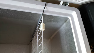
Terminals 3 & 4 are for the sensor that came with the
unit. The digital sensor is the black blob on the tip of the wires. The wires
are actual signal lines. I simply routed the sensor wire from the side of the frig, then tossed
the tip inside the frig. Because the wire is signal wire, it doesn’t matter it’s
exposed to the room temperature.

The overall power
wiring.
There are three parts which need power:
·
Circle (a) – LED indicator
·
Circle (b) – STC power supply
·
Circle (c) – switch that delivers power (red
line) to the frig
I used (e) and (d) to split the incoming power from (e)
·
(e) splits power to (d) and (a),
·
(d) redistributes power to (b) and (c)
Wiring Specifics:
Circle (a) shows the indicator wiring:
I got the original neutral white and original
black wire so the indicator has constant power.
Circle (b) shows the controller power wiring (they are
terminals 1&2 on STC-1000).
I got the piggybacked neutral white,
then got black power line from (d)
Circle (c) shows the power switch wiring (they are terminals
7&8 on STC-1000):
I got black power line from (d),
then the red line goes to the frig unit. As temperature changes, the switch
will connects/disconnects the power to the red line, and therefore control the refrigerator.
When all said and done, it was a refreshing experience! I got a digital controller and I can set the temperature to anything I like, although it's in celcius only :)
To configure the digital controller, you'll just need to google STC-1000 user manual. My unit came so cheap, it didn't even include a print out.
Please note the STC-1000 comes with power deliverying circuits. One for cooling (terminal 7&8). One for heating (terminals 5&6).
Since I only need the cooling, I left the heating terminals unwired. The purpose of both cooling and heating is to control an incubator, which requires constant temperature. When inside tempearture is above the set value, the cooling unit kicks in. (Obviously, I only have cooling unit). When it's below the set temperature, the heating unit will kick in.
The photos below shows how I made a replacement control panel with a cut out plastic part. The project costed me a whole weekend.


